The most famous color space (or color model to be very rigorous) in digital imaging is RGB. Commonly for each of the channels R(red), G(green) and B(blue) it is specified the amount of color using one byte.
The RGB color space has in part a physiological basis, our retina is especially sensitive to these colors. The problem is that the reality of visual perception is complicate and our ability to distinguish two colors does not depend faithfully on their distance in the RGB model. For instance, we have great capacity with some tones of green and little with others of blue. On the other hand the brightness contributes to distinguish more colors.
To reduce these issues, the JPEG format internally uses the
YCbCr
color space. Here Y is the luminance carrying achromatic information depending on the brightness, while
(Cb,Cr)
is the chrominance and both components embody the color information, biased respectively to blue and to red.
As Y is more important for our perception, in the JPEG format there is a more severe quantization in the chrominance. Even more, the latter may only be
computed for 1/2 or 1/4 of the pixels.
If you use GIMP, when exporting to JPEG you have
Advanced options > subsampling to control it.
A gray tone in RGB is (n,n,n) and corresponds in YCbCr to (n,128,128), so 128 in the channels Cb and Cr means no color. By this reason it is convenient to have in mind Cb'=Cb-128 and Cr'=Cr-128. Commonly, Y, Cb and Cr are also encoded by 1 byte each one. The relation between both color spaces varies with the authors and it is not exact because we force the numbers to be integers in [0,256). Following D. Salomon "A guide to compression methods" Springer-Verlag 2002, in the octave code below I use the linear relation
| Y = (77 R + 150 G + 29 B)/256 |
| Cb' = (-44 R - 87 G +131 B)/256 |
| Cr' = (131 R -110 G - 21 B)/256 |
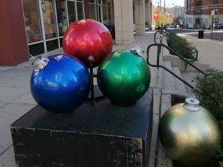
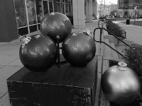
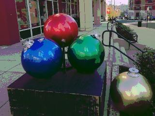
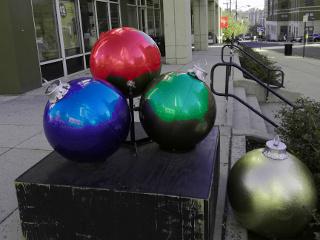
The code is to study the effect of the quantization on each channel on the 320x240 test image
| |
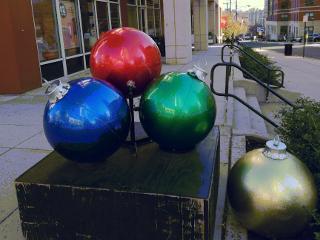
If we set all the channels of RGB except one to zero we get
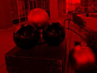 |
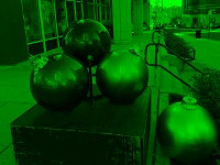 |
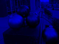 |
| G=B=0 | R=B=0 | R=G=0 |
Note that the red ball darkens when only the green channel is activated and vice-versa.
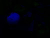
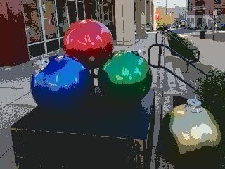
The analogue for YCbCr is:
 |
 |
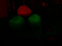 |
| Cb'=Cr'=0 | Y=Cb'=0 | Y=Cr'=0 |
Note that only the first one is informative about the global aspect of the photo. It gives a quite faithful B/W version of it.
Now let us check the quantization of the channels. The output images are in JPEG format that, as mentioned before, crops the chrominance channels but I have checked that there is not a significant difference with a lossless heavier format.
For a number in [0,256) if we establish
2r
levels (to use only r bits), in absence of more information about the image we should employ the uniform quantizer
d*floor(x/d)+d/2
with
d=28-r.
On the other hand, for
Cb' and Cr' that take values in [-128,128) and the extremes are not usually attained, is more convenient to use the uniform quantizer of the integers
d*floor(x/d+1/2)
(see my signal processing course).
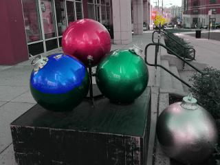
For
d=64
(2 bits instead of 8) the quantization on only one channel produces the following pictures. For comparison it is shown the original image to the left.
| | 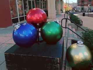 |
| Original | R quantized |
| |  |
| Original | G quantized |
| |  |
| Original | B quantized |
The changes in the B channel make little difference.
The analogue pictures for the YCbCr color spaces are:
| |  |
| Original | Y quantized |
| |  |
| Original | Cb' quantized |
| |  |
| Original | Cr' quantized |
This is the octave code that produces the images:
pkg load image


clear all


name = '../images/ballc.jpg';


% original image

ima = imread( name );


R = cast(ima(:,:,1),'double');

G = cast(ima(:,:,2),'double');

B = cast(ima(:,:,3),'double');


Y =      (77*R + 150*G + 29*B)/256;

Cb = 128 + (-44*R - 87*G +131*B)/256;

Cr = 128 + (131*R -110*G - 21*B)/256;


% Channel R

imwrite( ch_to_im(R,0*G,0*B, 0), 'col_R.jpg' )


% Channel G

imwrite( ch_to_im(0*R,G,0*B, 0), 'col_G.jpg' )


% Channel B

imwrite( ch_to_im(0*R,0*G,B, 0), 'col_B.jpg' )


% Channel Y

imwrite( ch_to_im(Y,128+0*Cb,128+0*Cr, 1), 'col_Y.jpg' )


% Channel Cb

imwrite( ch_to_im(0*Y,Cb,128+0*Cr, 1), 'col_Cb.jpg' )


% Channel Cr

imwrite( ch_to_im(0*Y,128+0*Cb,Cr, 1), 'col_Cr.jpg' )


%imwrite( ch_to_im(R,G,B, 0), 'col_.jpg' )


d=64

% Quantiz RGB

imwrite( ch_to_im(quan(R,d,0),G,B, 0), 'col_Rq.jpg' )

imwrite( ch_to_im(R,quan(G,d,0),B, 0), 'col_Gq.jpg' )

imwrite( ch_to_im(R,G,quan(B,d,0), 0), 'col_Bq.jpg' )


% Quantiz YCbCr

imwrite( ch_to_im(quan(Y,d,0),Cb,Cr, 1), 'col_Yq.jpg' )

imwrite( ch_to_im(Y,quan(Cb,d,1),Cr, 1), 'col_Cbq.jpg' )

imwrite( ch_to_im(Y,Cb,quan(Cr,d,1), 1), 'col_Crq.jpg' )
It calls to the function ch_to_im:
% Create image from channels

% C1, C2, C3 channels

% cf = 0->RGB  1->YCbCr


function res = ch_to_im( C1, C2, C3, cf )


  if cf== 1

    % YCbCr->RGB conversion

    R = -40/16237*C2 + 22173/16237*C3 + C1 - 2833024/16237;

    G = -5416/16237*C2 - 11363/16237*C3 + C1 + 2147712/16237;

    B = 28120/16237*C2 - 99/16237*C3 + C1 - 3586688/16237;

  elseif cf == 0

    % No conversion

    R = C1;

    G = C2;

    B = C3;

  end


  % RGB

  res = cat(3, R, G);

  res = cat(3, res, B);


  % integers in range 0, 255

  res = cast(res, 'uint8');


end
And also to the function quan:
% Two quantizers

% C = input

% d = interval/number of levels

% cf = 0-> uniform in [0,256)   1-> uniform in Z


function res = quan( C, d, cf )


  if cf == 0

    % uniform in [0,256)

    res = d*floor(C/d)+d/2;

  elseif cf == 1

    % uniform in [0,256)

    res = 128+d*floor((C-128)/d+1/2);

  end


end